

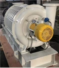


Structural chart:
See the following picture for the structure. The airflow direction of the series product is top-in and bottom-out.
Sequence | Component name | Sequence | Component name |
1 | Master oil tank | 7 | synchronizing gear |
2 | Main wallboard | 8 | Oil throwing component |
3 | Shell | 9 | Bearing component |
4 | Impeller and shaft assembly | 10 | Seal component |
5 | Auxiliary wallboard | 11 | Shaft seal component |
6 | Auxiliary oil tank |
Overview:
A. The No.3 machine shell is made of HT250 material and receives treatments of drawing temper and ageing treatment.
B. No.2 main wallboard and No.5 auxiliary wallboard are made of HT250 material and receive treatments of drawing temper and ageing treatment. The main wallboard and auxiliary wallboard as well as the machine shell constitute the machine body so as to form the air chamber by taper pin positioning.
C. The No.4 Impeller and shaft assembly, is made of QT500 high brand ductile iron by the numeral controlled equipment or uses HT300 as blade base and uses 40Cr to make the master shaft and then the hydraulic system is used to press them into a whole body.
D. The No.7 synchronizing gear made of 20CrMnTi by microfinishing, frequency quenching and then gear grinding. When it comes to tooth form, there are straight tooth and helical tooth to choose from.
E. No.9 bearing assembly, according to the difference between the positioning terminal and the free terminal, respectively adopts the double-row centripetal ball bearing and single row roller bearing. We can realize the precise positioning of the impeller component and the thermal expansion free outspread at the same time.
F. For No.10 seal assembly, we use the default piston ring seal, and can also offer different sealing arrangements according to client's requirement.